Back to the Drawing Board


Edit object
The Edit object tool is used to make complex changes to individual objects. When the Edit object tool is invoked, the cursor changes to the "pick object" cursor allowing you to select individual objects in your drawing. Once an object has been selected, a context dialog appears in the vicinity of the object showing which actions can be taken to modify the object. The actions available depend on the type of object selected.
Common options
Move vertex
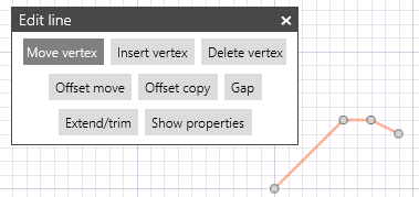
Applies to lines, doublelines, curves, polygons and arrows.
The Move vertex action allows you to modify the geometry of an object by moving the points that define it. This option is available when a line, doubleline, curve, polygon or arrow is selected. When the object is selected, circular "handles" are shown at each of the points that define the object. Moving these handles will move the corresponding vertex and change the geometry of the object.
When using touch, a handle can be selected by tapping it with your finger. When selected, the circle marker will become solid (filled in). The selected handle can then be moved using the arrow keys in the location panel or on the keyboard. They can also be repositioned by entering coordinates in the location panel.
Move point
Applies to rectangles, arcs, ellipses and dimensions.
The Move point action is similar to the Move vertex action except that it acts on the corners of rectangles, endpoints of circular arcs, axis points of ellipses, and dimension nodes.
Insert vertex
Applies to lines, doublelines, curves, polygons and arrows.
The Insert vertex action allows you to modify the geometry of linear objects by adding points to the path that defines it. This option is available when a line, polygon, doubleline, curve, arrow, or dimension object is selected.
When an object is selected, circular "handles" are drawn at each of the points that define its path. Points can be added to any segment in the path by locating a new point on that segment with the pointer device. These new points are similarly marked by circular handles. When in the Insert Point option, each vertex marked by a circular handle can be moved as described in the Move vertex section above.
Delete vertex
Applies to lines, doublelines, curves, polygons and arrows.
The Delete vertex action allows you to modify the geometry of linear objects by removing points from the path that defines it. This option is available when a line, polygon, doubleline, curve, arrow, or dimension object is selected. When an appropriate object is selected, circular "handles" are drawn at each of the points that define its path. These points can be deleted by tapping them with the pointer device.
Offset move
Applies to lines, doublelines, curves, polygons and arrows.
The Offset move (or "move parallel") action allows you to modify the geometry of an object by moving each segment by a given offset such that the new shape of the object is parallel to its old shape.
The offset distance is entered in text box in the lower portion of the context dialog. Positive offset values result in a move to the right. Negative offset values result in a move to the left.
Tapping the Apply button will apply the offset and move the selected object.
The selected object can also be offset by dragging any segment to a new location.
The object can be copied by pressing the SHIFT key when starting the drag action.
Offset copy
Applies to lines, doublelines, curves, polygons and arrows.
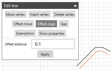
The Offset copy (or "copy parallel") action allows you to make a copy of an object whose shape is parallel to the shape of the original object, but offset by a given distance.
The offset distance is entered in text box in the lower portion of the context dialog. Positive offset values result in a move to the right. Negative offset values result in a move to the left.
Tapping the Apply button creates a parallel copy of the selected object. After the copy is created it becomes the new selection, so incremental offset copies are created each time the Apply button is tapped.
Parallel copies can also be created by dragging the selected object to a new location.
Gap
Applies to lines, doublelines, arrows and arcs.
The Gap action allows you to remove a segment of a linear object or circular arc. This option is only available when a line, doubleline, circle or arc object is selected.
When this action is invoked on an object, the object is highlighted. You add gaps by locating the gap endpoints on the object with the cursor. The new gap endpoints are identified by diamond markers. When gapping lines, doublelines and circles, gap segments are added to the object. When gapping arcs, the arc is split into two separate objects.
Extend/trim
Applies to lines, doublelines, polygons and arrows.
The Extend/Trim action allows you to extend (lengthen) or trim (shorten) a line segment by dragging one endpoint of the segment. The new location of the endpoint will be co-linear with the original segment. This option is available when a line, doubleline, polygon or arrow object is selected.
When this action is invoked on an object, circular "handles" are drawn at each of the points that define the object. These handles can be dragged as needed however the location of each handle is constrained to be co-linear with the original segment.
When a handle is selected at an intermediate vertex of the object, the segment on which the "pick point" lies will be extended or trimmed. The adjoining segment will no longer be parallel to its original position.
If the extension of the segment intersects with another object, Object Snap handles will appear at the intersection points.
Show Properties
The Show properties action shows the properties panel for the selected object. The properties panel shows each of the object's relevant properties and allows you to change them as needed. This is similar to the functionality of the Properties tool.
If the selected object is an instance of a group, the instance's properties are shown rather than the properties of the selected member (unlike the properties tool).
The and icons at the bottom of the properties panel let you change the display and pick priority for the selection.
Additional actions for Text objects
The following actions are only available when a text object is selected.
Change alignment points
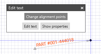
The Change alignment points action lets you move the points that define the location and orientation of text objects.
When this action is invoked on a text object, a triangle marker appears at its origin and a diamond marker appears at its alignment point. An arrow representing the text alignment vector is drawn connecting these points. Moving either of these points will change the alignment of the text object.
If the origin and alignment points are coincident (i.e. the same point) the "one-point" location mode is used and the text will be oriented according to its Angle property. Note that the alignment point can be changed even if the text was created using the "one-point" location mode.
Edit text
The Edit Text action allows you change the text content of a text object. When a text object is selected, an edit text box is drawn in the vicinity of the object. The text content can be changed by editing the contents of the text box.
The text can also be changed by modifying the contents of the text box in the text Properties panel.
Additional actions for Image objects
Move corner
The Move corner action is similar to the Move point action for rectangles.
For unscaled images (reference size value is not set), moving a corner changes the size of the bounding rectangle. The image will be drawn inside this box while keeping the aspect ratio (ratio of width to height) constant.
For scaled images (reference size value is set), moving a corner moves the entire image keeping the image scale constant.
Modify image
When an image object is selected the Modify image action is available. Selecting this action will invoke the Edit image dialog for the selected image object.
Additional actions for Groups and Symbols
The following actions are only available when an instance of a symbol or group is selected.
Some characteristics of a grouped object apply to all instances of the group while others apply only to the selected instance. Some group characteristics such as the origin and can only be changed when the group is unique (i.e. has only one instance). The group can be made unique using the Make this group unique action described below. This will break the association with the other instances allowing the the insert vector to be changed.
Make this group unique
The Make this group unique action breaks the association between the selected instance and any other instances of the same group, making the selected instance unique.
This action is only enabled when a non-unique group instance is selected.
Change alignment points
The Change alignment points action allows you to change the origin, exit point, and insert vector for the parent group of the selected instance. The insert vector determines how the group instance will be oriented when inserted using the Insert group, Linear array, or Radial array tools.
When this action is invoked, a triangle marker appears at origin of he selected instance and a diamond marker appears at its exit point. An arrow representing the group's insert vector is drawn connecting these points. Moving either of these points will change the insert vector.
This action is only enabled when a unique group instance is selected.
Fill in text attributes
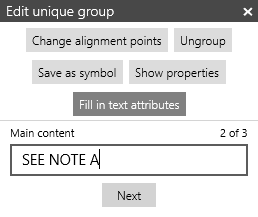
The Fill in text attributes action is used to fill in or modify text attributes in a group instance.
When this action is invoked, you will be prompted to supply values for each of the group's text attributes in a text box in the lower portion of the context dialog. Tapping the Next button below the text box will update the attribute's value and move to the next one. If you don't enter any text in the box, the attribute's value will not be changed. When the last attribute has been updated, tap the Done button to continue.
If the selected group does not contain text attributes, this action will not be available in the context dialog.
For more information about attributes see Text Attributes in Groups.
Save as symbol
The Save as symbol action saves the parent group of the selected instance as a Symbol.
When this action is invoked, the standard Window Save file picker is shown. This allows you to specify a name and location for the symbol file.
For more information about symbols, see the Symbols and groups documentation.
Ungroup
The Ungroup action breaks apart a group making each of its members discrete objects.