Back to the Drawing Board
Tutorial: Drawing arcs
The tutorials in this section cover various ways to draw circular and elliptical Arcs. There are a number of construction methods that can be used to draw arcs. This makes them deserving of a separate tutorial section.
Arcs can be drawn by locating points with your cursor (mouse, stylus or your finger), entering coordinates (absolute, delta or polar), or by using the arrow keys on your keyboard. Each of these techniques is covered in Drawing lines and entering points. In the tutorials that follow you will be asked to enter points at specific coordinates. You can use whichever input technique you prefer to enter the points.
Task 5.1: Set your view
The tutorials in this section assume that you have created a full-scale metric ISO A4 size drawing and have your device in the "landscape" orientation. You can review the steps to create this drawing in the Create a full-size metric A4 drawing sheet task.
In this exercise we're simply setting the view to show an enlarged area in the center part of your drawing. All of the exercises in this section will use this view.
- Verify that the control panel is visible. If it's not, make it visible by tapping the "Control panel" button in the bottom right app bar.
- Verify that the grid is visible. If not, tap the "Grid" button in the Quick access panel.
- Verify that the rulers are visible. If not, tap the "Rulers" button in the Quick access panel.
- Verify that the full extents of your drawing are visible. If not, tap the "Zoom all" button in the Quick access panel.
-
Tap the "Zoom in" button in the Quick access panel.
Depending on your screen size, you should see an area that covers roughly
(60, 80)to(220, 150).
Task 5.2: Draw circular arcs by locating center points
This tutorial shows two construction methods that can be used to create arcs when the center point is known.
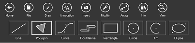
- Select the Draw tools by tapping the Draw button in the top app bar.
- Select the Arc tool by tapping the Arc button in the command bar.
- Tap the Layer button in the bottom app bar (or select from the "Layer" menu in the Tool panel). Select "Layer 005" (by default, a black dashed line).
- Tap the Fill button in the bottom app bar (or select from the "Fill" menu in the Tool panel) and verify that "No fill" is selected.
- Tap the Construct button in the bottom app bar (or select from the "Construct" menu in the Tool panel). Select Center/start/end.
-
Enter a point at
(110, 130). Note that a "rubber band" arrow follows the cursor with its base anchored at(110, 130). This is the radius vector for the arc. -
Move the cursor to
(110, 140)and enter a point. Note that a rubband arc centered at(110, 130)follows the cursor. The distance between the center point and(110, 140)defines the radius. -
Note that if you move the cursor to the left of
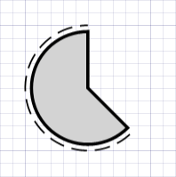
(110, 140), the arc sweeps counter-clockwise; if you move the cursor to the right, the arc sweeps clockwise. Move the cursor to the left of(110, 140), then to(120, 120)and enter a point.You should now have a black dashed arc with a radius of 10 mm, start angle at 90 degrees, and an included angle of 225 degrees.If you are entering points by coordinate, you can tap the left arrow button in the coordinate panel to move the cursor left and set the counter-clockwise direction. - Tap the Layer button in the bottom app bar (or select from the "Layer" menu in the Tool panel). Select "Layer 002" (by default, a medium thick black line).
- Tap the Fill button in the bottom app bar (or select from the "Fill" menu in the Tool panel). Choose Select a new color from the menu and select "Light gray" using the Color picker
- Tap the Construct button in the bottom app bar (or select from the "Construct" menu in the Tool panel) Select Radius. Note that the Radius app bar button is now enabled.
- Tap the Radius button in the bottom app bar (or select from the "Radius" menu in the Tool panel) Enter 9 for the the "Radius" value.
-
Enter a point at
(110, 130). Note that a "rubber band" arrow representing the radius vector follows the cursor with its base anchored at(110, 130). Note also that the length of the radius vector is fixed at 9 mm. -
Move the cursor to
(110, 140)(the end of the previously created arc) and enter a point. Note that a rubband arc with a radius of 9 mm centered at(110, 130)follows the cursor. -
Move the cursor to the left of
(110, 140)(setting the arc direction to counter-clockwise), then to(120, 120)and enter a point. You should now have a black arc filled with light gray, a radius of 9 mm, start angle at 90 degrees, and an included angle of 225 degrees.
Task 5.3: Draw circular arcs by locating center points, radius and angles
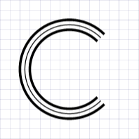
This tutorial shows how to create arcs by specifying their radius, start angle and included angle values. With these values explicitly set, all that is needed is a center point to define the arc.
- Select the Draw tools by tapping the Draw button in the top app bar.
- Select the Arc tool by tapping the Arc button in the command bar.
- Tap the Construct button in the bottom app bar (or select from the "Construct" menu in the Tool panel). Select Radius & angles.
- Tap the Layer button in the bottom app bar (or select from the "Layer" menu in the Tool panel). Select "Layer 002" (by default, a medium thick black line).
- Tap the Fill button in the bottom app bar (or select from the "Fill" menu in the Tool panel). Select "No fill".
- Tap the Radius button in the bottom app bar (or select from the "Radius" menu in the Tool panel) Enter 10 for the the "Radius" value.
- Tap the Angles button in the bottom app bar (or select from the "Radius" menu in the Tool panel) Enter 45 for the the "Start angle" value and 270 for the "Included angle" value.
-
Enter a point at
(110, 90). Note that the arc appears immediately since only one point is required to locate the arc. - Tap the Radius button in the bottom app bar (or select from the "Radius" menu in the Tool panel) Enter 8 for the the "Radius" value.
-
Enter another point at
(110, 90). A smaller arc appears concentric to the first. - Tap the Layer button in the bottom app bar (or select from the "Layer" menu in the Tool panel). Select "Layer 001" (by default, a thin black line).
- Tap the Radius button in the bottom app bar (or select from the "Radius" menu in the Tool panel) Enter 9 for the the "Radius" value.
-
Enter another point at
(110, 90). You should now have a thin black arc between the two previously created arcs.
Task 5.4: Draw circular arcs by locating three points
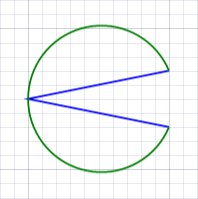
This tutorial shows how to create an arc that passes through three points. We will start by drawing a line connecting the three points.
- Select the Draw tools by tapping the Draw button in the top app bar.
- Select the Line tool by tapping the Line button in the command bar.
- Tap the Construct button in the bottom app bar (or select from the "Construct" menu in the Tool panel). Select Multi segment.
- Tap the Layer button in the bottom app bar (or select from the "Layer" menu in the Tool panel). Select "Layer 010" (by default, a blue line).
-
Enter points at
(160, 126),(140, 130)and(160, 134). You should now have a two-segment blue line shaped like a sideways "V" pointing to the left. - Select the Draw tools by tapping the Draw button in the top app bar.
- Select the Arc tool by tapping the Arc button in the command bar.
- Tap the Construct button in the bottom app bar (or select from the "Construct" menu in the Tool panel). Select Three point.
- Tap the Layer button in the bottom app bar (or select from the "Layer" menu in the Tool panel). Select "Layer 009" (by default, a green line).
- Tap the Fill button in the bottom app bar (or select from the "Fill" menu in the Tool panel). Select "No fill".
-
Enter a point at
(160, 126)(the first vertex of the blue line). A circular marker should appear at this point. -
Enter a point at
(140, 130)(the second vertex of the blue line). Another circular marker appears at this point and a rubber band arc follows the cursor passing through the previous markers and ending at the cursor. -
Enter a point at
(160, 134)(the last vertex of the blue line). You should now have a green arc passing though each vertex of the blue line.
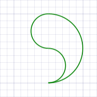
Task 5.5: Draw semi-circles by locating two points
This tutorial shows how to create semi-circles (half circles, or arcs with an included angle of 180 degrees) by specifying diametrically opposite points.
- Select the Draw tools by tapping the Draw button in the top app bar.
- Select the Arc tool by tapping the Arc button in the command bar.
- Tap the Construct button in the bottom app bar (or select from the "Construct" menu in the Tool panel). Select Semi circle.
- Tap the Layer button in the bottom app bar (or select from the "Layer" menu in the Tool panel). Select "Layer 009" (by default, a green line).
- Tap the Fill button in the bottom app bar (or select from the "Fill" menu in the Tool panel). Select "No fill".
-
Enter a point at
(150, 80). A rubber band counter-clockwise semi-circle with one endpoint anchored at(150, 80)follows the cursor. -
Enter a point at
(150, 100). A green semi-circle should appear sweeping counter-clockwise from(150, 80)to(150, 100). -
Enter points at
(150, 100),(150, 90),(150, 80)and(150, 90). You should now have three semi-circles forming a green "apostrophe" shape.
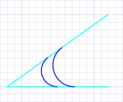
Task 5.6: Draw circular arcs tangent to two intersecting lines
This tutorial shows how to create an arc tangent to two intersecting lines (a fillet). Fillets are created by locating the three points that define the two intersecting lines. We will start by drawing lines that represent the two tangent line segments.
- Select the Draw tools by tapping the Draw button in the top app bar.
- Select the Line tool by tapping the Line button in the command bar.
- Tap the Construct button in the bottom app bar (or select from the "Construct" menu in the Tool panel). Select Multi segment.
- Tap the Layer button in the bottom app bar (or select from the "Layer" menu in the Tool panel). Select "Layer 011" (by default, a cyan line).
-
Enter points at
(204, 120),(176, 120)and(204, 140). You should now have a two-segment cyan line connecting the three points. - Select the Draw tools by tapping the Draw button in the top app bar.
- Select the Arc tool by tapping the Arc button in the command bar.
- Tap the Construct button in the bottom app bar (or select from the "Construct" menu in the Tool panel). Select Fillet. When using this construction method the arc is tangent to the first line segment at the first point entered.
- Tap the Layer button in the bottom app bar (or select from the "Layer" menu in the Tool panel). Select "Layer 010" (by default, a blue line).
- Tap the Fill button in the bottom app bar (or select from the "Fill" menu in the Tool panel). Select "No fill".
-
Enter a point at
(190, 120)(the mid-point of the first cyan line). A rubber band line representing the first tangent line follows the cursor from(190, 120). -
Enter a point at
(176, 120)(the intersection of the two cyan line segments). A rubber band line representing the second tangent line follows the cursor from(176, 120). A rubber band arc tangent to both lines also follows the cursor. -
Enter a point at
(204, 140)(the end point of the second cyan line segment). You should now have a blue arc tangent to the two cyan lines. The arc is tangent to the first line segment at its mid-point(190, 120). - Tap the Construct button in the bottom app bar (or select from the "Construct" menu in the Tool panel). Select Fillet & radius. When using this construction method the arc is tangent to both line segments with a fixed radius.
- Tap the Radius button in the bottom app bar (or select from the "Radius" menu in the Tool panel) Enter 6 for the the "Radius" value.
- Tap the Layer button in the bottom app bar (or select from the "Layer" menu in the Tool panel). Select "Layer 009" (by default, a green line).
-
Enter a point at
(190, 120)(the mid-point of the first cyan line). A rubber band line representing the first tangent line follows the cursor from(190, 120). -
Enter a point at
(176, 120)(the intersection of the two cyan line segments). A rubber band line representing the second tangent line follows the cursor from(176, 120)A rubber band arc with a radius of 6 mm tangent to both lines also follows the cursor. -
Enter a point at
(204, 140)(the end point of the second cyan line segment). You should now have a green arc with a radius of 9 mm tangent to both cyan lines.
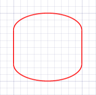
Task 5.7: Draw elliptical arcs
This tutorial shows how to draw elliptical arcs. The construction methods used to draw elliptical arcs are exactly the same methods used to draw ellipses. Ellipses become elliptical arcs when the ellipse's Included angle is set to something less than 360 degrees. In this tutorial, we will draw two 2:1 semi-elliptical arcs connected by line segments. This shape could represent a pressure vessel in a Piping and Instrument Diagram (P&ID). We will start by drawing the line segments.
- Select the Draw tools by tapping the Draw button in the top app bar.
- Select the Line tool by tapping the Line button in the command bar.
- Tap the Construct button in the bottom app bar (or select from the "Construct" menu in the Tool panel). Select Single segment.
- Tap the Layer button in the bottom app bar (or select from the "Layer" menu in the Tool panel). Select "Layer 008" (by default, a red line).
-
Enter points at
(180, 85),(180, 95),(200, 95)and(200, 85). You should now have two parallel 10 mm lines 20 mm apart. - Select the Draw tools by tapping the Draw button in the top app bar.
- Select the Ellipse tool by tapping the Ellipse button in the command bar.
- Tap the Construct button in the bottom app bar (or select from the "Construct" menu in the Tool panel). Select Axis.
- Tap the Layer button in the bottom app bar (or select from the "Layer" menu in the Tool panel). Verify that "Layer 8" is still selected.
- Tap the Fill button in the bottom app bar (or select from the "Fill" menu in the Tool panel). Select "No fill".
- Tap the Size & angles button in the bottom app bar (or select from the "Size & angles" menu in the Tool panel) Enter 2 for the the "Major:minor ratio" value, 180 for the "Included angle" value and 0 for the "Start angle" value. Note that the "Start angle" option is disabled when the "Inlcuded angle" value is 360.
-
Enter a point at
(180, 95)(the top endpoint of the left line segment). Note that a rubber band ellipticial arc follows the cursor. -
Enter a point at
(200, 95)(the top endpoint of the right line segment). A red semi-ellipse should connect the top endpoints of the line segments. -
Enter points at
(200, 85)and(180, 85)(the bottom endpoints of the line segments). You should now have a closed shape consisting of two red semi-ellipses connected by two red line segments.