Back to the Drawing Board


Edit group definition
The Edit group tool modifies the definition of a group. The group is identified by selecting an instance (or copy) of the group in the active drawing. Once a group is selected, individual members can be moved or deleted; additional objects can be added; the origin and insert alignment points can be moved; and properties of the group or individual members can be viewed or changed. If there is more than one instance (or copy) of the group, you can choose to make the changes globally (affecting all copies) or only to the selected instance. If you choose to modify only the selected instance, a new group will be created that no longer shares the original groups definition. If a single ungrouped object is selected, you can choose to convert that object to a group.
When an object is selected in the Edit group tool, the object will be highlighted and one of three slightly different context dialogs will be shown, depending on the type of object.
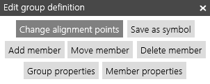
If the selected object is a single instance of a group (with no other copies), the context dialog will show seven options for acting on the group. This is the normal case.
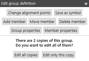
If the selected object is a group with more than one instance, you will be given the option (as shown on the right) to modify all instances of the group, or to modify only the selected instance. If you choose to modify only the selected instance, a new group will be created that is identical to the other group but has only one instance (the one selected). Changes to the original group will no longer affect the new group and vice-versa. If you do not specifically choose to modify only the selected instance, all modifications will be made globally.
If the selected object is not a group instance you will be given the option to create a group from that object. Naturally, if you do not create a group, none of the group editing actions will be available.
If the selected instance has been transformed (scaled or rotated) certain options will be disabled. If you need to apply one of the disabled actions, select an untransformed instance of the group, or create an untransformed instance, and make the desired modifications globally to that instance. You can reset an object's transformations using the Select objects tool.
Change alignment points
Each group has three reference points that are used to define the position and orientation of group instances. These points are identified by markers when the Change alignment points action is selected. The location of these points can be changed by dragging the markers to a new location.
When a group instance is added to a drawing using the Insert group tool, the new instance is located by aligning it's origin with the location of the cursor. The location of the origin is marked by a triangle marker.
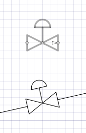
Additionally, when a group instance is inserted onto a Line or Doubleline segment, the orientation of the instance can be aligned with the line segment, and the segment can be gapped to accommodate the instance. This is done by defining insert alignment points on the group. The instance is rotated so that the alignment points are aligned with the segment. The segment will be gapped at the alignment points if the Insert instances into line segments checkbox is checked.
The insert alignment points are identified by diamond markers. The alignment vector is shown as an arrow connecting these points. The alignment vector can be changed by moving the alignment points.
By default, the alignment points are coincident with the origin of the group. If the alignment points are coincident, the insert-into-line feature is disabled. The instance will not be oriented and the segment will not be gapped when the instance is inserted onto a line segment. When all three markers are coincident, dragging from this location will first move the origin, then the alignment end point, and finally the alignment start point. You may need to temporarily move some markers out of the way to select the marker you want to move.
This action is not available if the selected instance is transformed.
Add member
The Add member action allows you to add additional members to the group. After choosing this action, any objects selected will be added to the group. This action is not available if the selected instance is transformed.
Move member
The Move member action allows you to change the location of individual members of the group. After selecting this action, members can be moved by dragging them to the desired location. This action is not available if the selected instance is transformed.
Delete member
The Delete member action allows you to delete members of the group. Members are deleted by first selecting the individual member, then tapping the Delete member button. The Delete member button is disabled if the group contains only one object.
Group properties
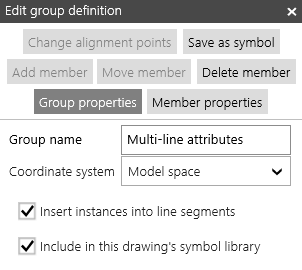
The Group properties action allows you view and change properties of the group. The group properties are as described below.
Group name The group name provides an identifier for the group.
Coordinate system When inserting symbols that were created in other drawings, the symbol can be defined using the "paper space" or "model space" coordinate system of the original drawing. If the scale and/or units of the current drawing are different than the scale or units of the drawing in which the symbol was created, the Coordinate system value determines the symbol's size in the new drawing.
If Paper space is selected, the symbol will be the same size as the original when printed or plotted. This would be appropriate for symbols such as title blocks or section titles.If Model space is selected, the symbol will be the same size in real world units. For example, if a door symbol was created in a 1/8"=1-0 drawing and inserted in a 1/4"=1-0 drawing, the door would be twice as big in the new drawing.
Insert instances into line segments Certain types of symbols are meant to be included in linear structures. Examples are resistor symbols in electrical schematics, gate valves in piping drawings, and doors in floor plans. The Insert instances into line segments option is used in conjunction with the insert vector to enable this behavior. If Insert instances into line segments is checked and the symbol is inserted onto a line or doubleline segment, the symbol will be rotated such that its alignment vector is aligned with the line segment. In addition, the sub-segment of the line segment will be removed (gapped) between the alignment points.
Include in this drawing's symbol library If the Include in this drawing's symbol library option is checked, the symbol will be included in the current drawing's symbol library.
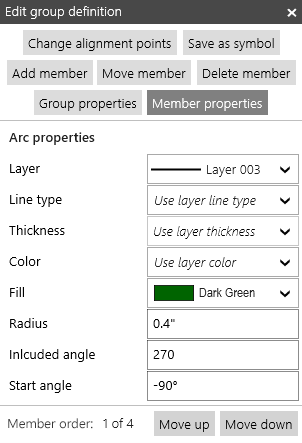
Member properties
The Member properties action allows you view and change properties of individual members of the group. The properties that are shown depend on the type of member selected. The properties shown are the same as those shown for ungrouped objects when viewing properties in the Edit object or Propeties tools.
Under the member properties panel, you will find a Member order option. The member order value is analogous to the display order value for ungrouped objects. The member order value controls the order in which members are displayed an picked within the group.