Back to the Drawing Board


Dimension
The Dimension tool draws automatic dimensions. There are currently five supported types of dimensions, linear baseline, linear incremental, point-to-point, incremental angular, and baseline angular. The sequence of points needed to define the dimension object depends on the type of dimension being created. The dimension tool calculated distances and angles based on the model coordinate system of the drawing. The format and precision of the dimension text can be set in the general settings panel.
The options described below can be found in the bottom app bar or in the control panel.


- Incremental: Linear dimensions are measured for a series of points along a single line. Each distance is measured along the reference line from the previous point.

- Baseline: Linear dimensions are measured for a series of points along a single line. Each distance is measured along the reference line from the first point.

- Point to point: Linear dimensions are measured for a series of connected points with distances measured between each point.

- Angular: Angular dimensions are measured for a series of arc segments with a common center point. Each arc segment is measured from the end of the previous arc segment.

- Baseline angular: Angular dimensions are measured for a series of arc segments with a common center point. Each arc segment is measured from the beginning of the first arc segment.


Defining the dimension object
The diagrams that follow show the points needed to define the dimension nodes for each dimension type. The location of these nodes can be changed using the edit object tool. Moving the dimension nodes will change the dimension values as appropriate.
Incremental
The Incremental linear dimension type requires a minimum of four points to describe the dimension object. The first two points define the reference line along which all of the dimensions are measured. The third point defines the location of the dimension lines. The points that follow define dimension nodes, each of which will generate a new dimension measured from the previous node along the reference line.
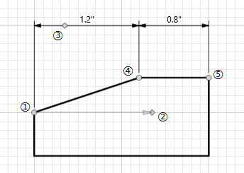
The definition of each of these nodes are illustrated by the diagram to the right.
- The anchor point of the dimension (identified by a circle marker) and the start point of the reference line. This point also defines the start of the first extension line. All of the extensiion lines will be perpendicular to the reference line.
- The end point of the reference line node (identified by a diamond marker). When locating this point, an arrow representing the reference line will be drawn from the anchor point to this point. All dimension distances will be measured along this line.
- The location of the dimension line (identified by a diamond marker). All of the dimension lines will pass through this point.
- The second dimension node (identified by a circle marker). This point defines the start of the next extension line and the end of the distance to be measured. This point can be repeated as desired. Each additional point generates a new arc segment.
- Additional dimension nodes (identified by a circle marker). This point can be repeated as desired. Each additional point generates a new incremental dimension.
Baseline
The Baseline linear dimension type requires a minimum of four points to describe the dimension object. The first two points define the reference line along which all of the dimensions are measured. The third point defines the location of the first dimension line. Additional dimension lines will be "stacked" above this line. The spacing between dimension lines is based on the size of the dimension text. The points that follow define dimension nodes, each of which will generate a new dimension measured from the anchor point along the reference line.
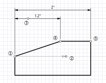
The definition of each of these nodes are illustrated by the diagram to the right.
- The anchor point of the dimension (identified by a circle marker) and the start point of the reference line. All of the dimensions in this object will be measured from the anchor point along the reference line. This point also defines the start of the first extension line. All of the extensiion lines will be perpendicular to the reference line.
- The end point of the reference line node (identified by a diamond marker). When locating this point, an arrow representing the reference line will be drawn from the anchor point to this point. All dimension distances will be measured along this line.
- The location of the first dimension line (identified by a diamond marker). Any additional dimension lines will be "stacked" above the first dimension line.
- The second dimension node (identified by a circle marker). This point defines the start of the next extension line and the end of the distance to be measured. This point can be repeated as desired. Each additional point generates a new arc segment.
- Additional dimension nodes (identified by a circle marker). This point can be repeated as desired. Each additional point generates a new baseline dimension.
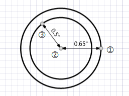
Angular
The Angular dimension type requires a minimum of four points to describe the dimension object. The first point defines the center of the arc about which the angles are measured. The second point defines the first dimension node and the start point for the first extension line. The third point defines the radius of the arc through which all of the dimension arcs will pass. The points that follow define dimension nodes, each of which will generate a new angular dimension.
The angle value is the included angle between the line connecting the center point with the current node and the line connecting the center point with the previous node.
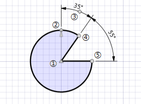
The definition of each of these nodes are illustrated by the diagram to the right.
- The center of the arc (identified by a triangle marker) around which the angles are measured.
- The first dimension node (identified by a diamond marker). This point defines the start of the first extension line and the beginning of the first arc segment.
- The location of the first dimension (identified by a diamond marker). The dimension arc will pass through this point.
- The second dimension node (identified by a circle marker). This point defines the start of the next extension line and the end of the arc segment to be measured. This point can be repeated as desired. Each additional point generates a new arc segment.
- Additional dimension nodes (identified by a circle marker). This point can be repeated as desired. Each additional point generates a new arc segment.
Baseline angular
The Baseline angular dimension type requires a minimum of four points to describe the dimension object. The first point defines the center of the arc about which the angles are measured. The second point defines the first dimension node and the start point for the first extension line. The third point defines the radius of the arc through which the first dimension arc will pass. Additional dimension lines will be "stacked" above this arc. The spacing between dimension arcs is based on the size of the dimension text. The points that follow define dimension nodes, each of which will generate a new angular dimension.
The angle value is the included angle between the line connecting the center point with the current node and the line connecting the center point with the first node.
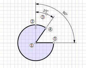
The definition of each of these nodes are illustrated by the diagram to the right.
- The center of the arc (identified by a triangle marker) around which the angles are measured.
- The first dimension node (identified by a diamond marker). This point defines the start of the first extension line and the beginning of the first arc segment.
- The location of the first dimension (identified by a diamond marker). The first dimension arc will pass through this point.
- The second dimension node (identified by a circle marker). This point defines the start of the next extension line and the end of the arc segment to be measured. This point can be repeated as desired. Each additional point generates a new arc segment.
- Additional dimension nodes (identified by a circle marker). This point can be repeated as desired. Each additional point generates a new arc segment.
Point to point
The Point to point dimension type requires a minimum of two points to descibe the dimension object. The dimension line starts at the first point and ends at the second point. The dimension value is the distance between these two points. Additional points can be entered defining new point-to-point dimensions.
Unlike the Baseline and Incremental types, the dimensions are not required to be colinear. There is no reference line. The dimensions measure the distances between any set of arbitrary connected points.
The definition of these nodes are illustrated by the diagram to the right.
- The start point of the first dimension (identified by a circle marker). This point can be repeated as desired. Each additional point generates a new arc segment.
- The endpoint of the first dimension start point of the next dimension (identified by a circle marker).
- Each additional point generates a new dimension measured from the previous node.